Lock-Up Devices (LUDs), also sometimes called Shock Transmission Units (STUs), are a component from the same general technology base of fluid dampers, but unlike a fluid damper, the LUD does not dissipate energy. Rather, the LUD effectively acts as a dynamic brace to literally “lock” multiple masses together under seismic or wind transients. When equipped with Lock-Up Devices, a multiple mass structure essentially acts like a single, monolithic mass when a transient event occurs.
Lock-Up Device designs are extremely simple, and available sizes range from 1 ton to 2,000 tons of force, and displacements up to plus or minus 60 inches.
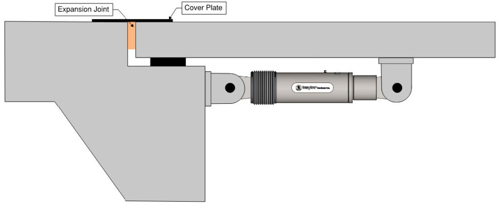
Contact us today to learn more about Lock-Up Devices. Our team is ready to help answer any questions you may have about how these devices work or implementing them into a project.
Lock-Up Devices can be used on bridges of all types. In the structural engineering field, these devices have become widely used to restrict the motion of bridges located in the Eastern and Central United States, notably in areas classified as Seismic Zones 1-3. Many of these bridges also have the requirement to withstand wind loads from hurricanes and/or tornadoes, plus loads from truck or train braking, where bridge motion must be limited over a sustained period of several hours.
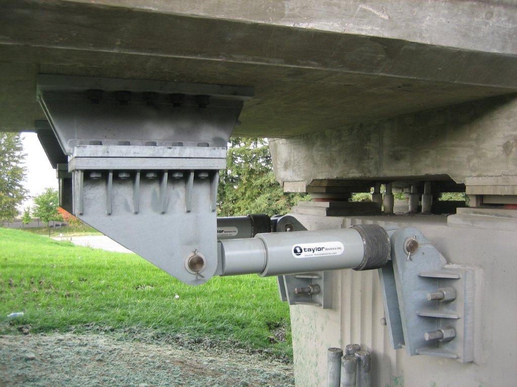
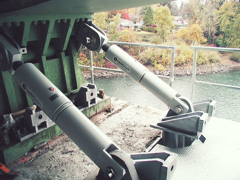
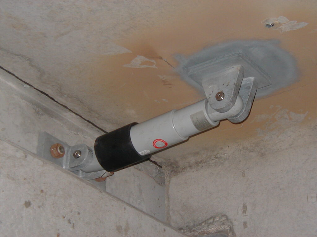
Base isolated structures in high seismic areas and fixed base buildings subjected to wind storm or low-level seismic transients. Buildings that are located close to one another and subjected to “pounding” problems, which can occur in any area of seismic or wind storm risk, may benefit from LUDs.
Another major area of application is the use of LUDs between discrete sections of a structure, thus allowing loads to be shared among individual masses during a transient event.
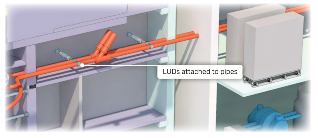
Lock-Up Devices can be attached to piping in a power plant, allowing for movement during thermal expansion, but will become rigid and hold the pipes in place during as seismic event.
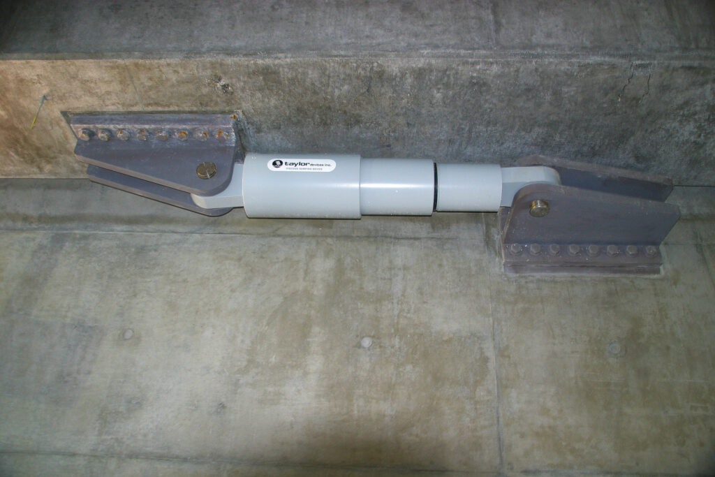
The piston rod of a Taylor Lock-up Device (LUD) extends entirely through both ends of the fluid chamber. When the LUD is stroked, there is no net oil compression or displacement by the piston rod. This eliminates the need for external valves, piping and accumulator, all a potential source for maintenance and malfunction. In addition, the balanced rod design supports the piston rod at both ends, greatly increasing its ability to withstand off-center or bending loads. A third advantage of the balanced rod is that both compression and extension orifices are identical, with no biasing required to allow for piston rod displacement. The piston rod is fully machined from solid PH type stainless steel, is through hardened, then super finished to a mirror-like surface finish.
• Highly resistant to sideload
• Zero net oil displacement
• Stainless steel, through-hardened
• Superfinished piston rod
• Simplified design, fewer parts, greater reliability
• Billet machined for higher strength
• Large diameter machined threads, polished undercuts for maximum strength
• No bolts, snap rings, welds, or tie rods used for structural joints
• Environmentally protected
The Taylor Devices hydraulic design combines a hydraulically balanced piston rod with a positive internal pressure of 2,000 to 4,000 psi. This positive pressure provides an inherent compressed internal fluid reservoir while at the same time activating Taylor Devices’ patented pressure seals and eliminating air voids. This provides immediate force transmission for maximum effectiveness. In addition, positive internal pressure precludes leakage over long periods of time and minimizes the effect of radiation shrinkage on seals. The ability of the positive pressure to exclude dirt, moisture, and air from the LUD is far superior to other standard low pressure designs.
• Fully machined from billet material
• Material for thermal and radiation resistance
• Design inhibits extrusion